Wednesday, September 30, 2015

Pedal box

Not the easiest thing to fit!

I needed help nipping up the nuts and bolts that held the pedal box and the master cylinders in place. Barry Clark came to borrow a spanner for his hedge trimmer and was roped in! Barry held the nuts in the off-side compartment, whilst I tightened up the bolts from the foot well. Thanks Barry, couldn't have done it without you.
The pedal box with the bar clearly visible above the accelerator pedal
A view from the other side showing the link bar
The accelerator pedal was finally fixed to the electronic pedal with the link bar. The accelerator link bar clears the hole side by 2mm at the closest point. The bar consists of 180mm of 6mm threaded bar (the bar supplied by GD was too short, so I had to use some threaded bar of the same diameter which, luckily, I had in the garage), two 6mm rose joints and two locking nuts, so easy enough to make up yourself.

The accelerator pedal travel was about 85mm, rather than the 100mm I had aimed for, so I hope it is ok. Andy says to leave it at present.

The big washer and bolt is to hide my drilling mistake!

Tuesday, September 29, 2015

Cobra windscreen, demister slots and heater

Windscreen

Before I started any other work, I polished the scuttle with G6, then G3 Farecla compound so that I wouldn't catch the polishing bonnet on any new holes/slots.

The windscreen was fed in to the holes cut previously for the windscreen stanchions. This is a two person job as it is £500 + of kit and Mrs C helped here. The holes needed opening out a little to take the stanchions.
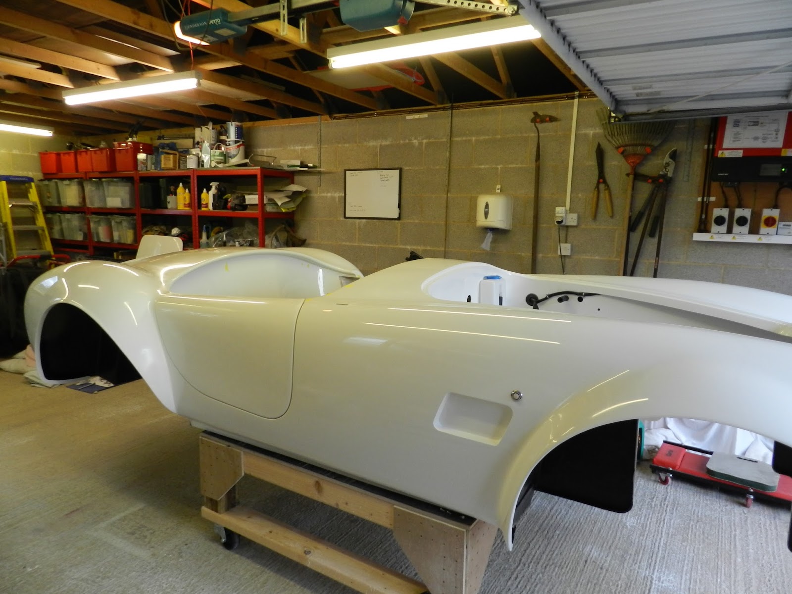
Starting to look like a car now with the windscreen fitted
Demist slots

These may or may not be marked on the body by GD! Mine were not. I measured the ones on Keith Akerman's car, pre-marked by GD, to get the positions.

First I put some masking tape on the scuttle where the demist vent would go. The outer screw hole of each vent were positioned 220mm in from the windscreen mounting hole, 80mm back from the cockpit roll (measured at the centre line of the vent hole). The second hole was marked through the demist escutcheon. The end furthest from the windscreen stay was also positioned 80mm from the roll. I checked the measurements from a centre line just to be sure. I had used different measurements each side! Luckily I measured twice and cut once!
Centre line marked on the scuttle
I drilled multiple holes in the scuttle and did the final cut with the trusty Dremel.
Demist vent with the escutcheon fitted

The cut out edges of the demist slots were spray painted satin black, before the escutcheons were fitted and bolted though to the fish tail part of the demist vents (holes already tapped in the fish tail vents).

I also painted the side vents in the wings whilst I was on with it.
Off side dummy 'vent' painted in satin black
Heater pipes

Fishtails can be seen mounted here under the scuttle
Once these vents were cut, the escutcheons and fish tails fitted, the heater pipes were put in place. The heater pipes can be fitted to the heater as you wish, as both holes from the heater deliver warm air at the same rate. I took the hose from one hole to the centre of the transmission tunnel and cut it there. A 'Y' piece, made by Keith Akerman, was fitted here. Equal length hoses (to ensure equal volume of air gets to each vent) were then cut and connected from the 'Y' piece to the fish tail demist vents and secured with tie wraps.
Demist pipes in place
A second hose was connected to the other outlet of the heater and again taken to the centre of the transmission tunnel. Here it was connected to the second 'Y' piece and equal length hoses (the supplied hose was not quite long enough) were attached, again using tie wraps to secure, for the foot well vents. I cut these pipes longer than it appeared necessary, so that the top part of each louvre vent could be attached to the under dash tray before fixing this in place.

Pedal box

Using a fly by wire pedal for the Chevy LS engine is not straight forward on the GD Cobra.

The fly by wire pedal cannot be used as it is, because there is insufficient space in the driver's foot well to use it as it is and its travel is not enough for a progressive pedal. Instead it needs to be adapted and mounted in the off side wheel arch compartment, at the other side of the driver's foot well. A bar is used to connect the electronic pedal to the accelerator pedal on the GD pedal box.

The GD pedal box was installed as normal, after drilling a 6mm hole in the accelerator pedal 10mm down the top part of the accelerator pedal and in-line with the pivot bar i.e. 90 deg to the pedal travel. This was a tricky job and require a drill stand and a drill clamp to hold the pedal - drilling a 6mm hole in a 10mm round bar was not easy! I used gradually bigger drill bits to make the hole.

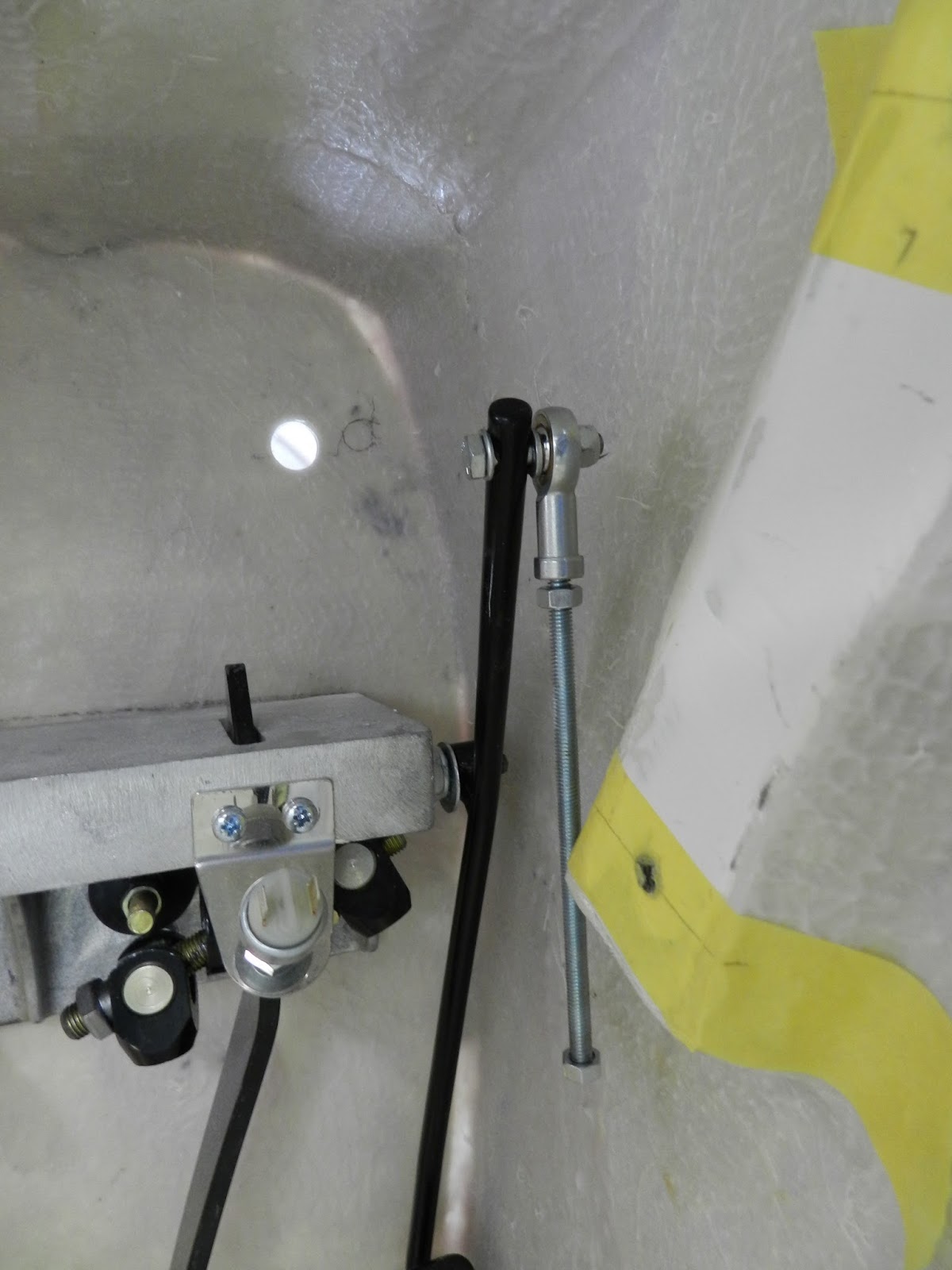
A 20mm hole was then drilled through the bulkhead in line with the rose joint. I got this wrong the first time and will cover up my mistake with a bolt and washers to fill in the hole!
Bar attached to the accelerator pedal - correct hole marked!
I kept the new hole near to the right side of the driver foot well, to allow the electronic pedal arm to remain as long as possible to maximise the leverage. I was aiming for 100mm of accelerator pedal travel. The electronic pedal only moves by about 55mm.

The foot plate on the electronic pedal was removed. The electronic pedal arm was shortened to fit in the compartment and a new hole drilled. However, I kept the arm as long as possible.
Pedal arm shortened and 6mm hole drilled
The electronic pedal was then fixed horizontally, above the brake and clutch master cylinders, to the bulkhead in the off side wheel arch compartment. Once fully adjusted and fixed in place I will post some photos.

The threaded bar has the two rose joints attached one at each end. Lock nuts are used to secure the rose joints in their final place. One end of the bar was fed through the hole in the bulkhead and attached to the accelerator pedal using a 6mm bolt through the rose joint and the other end was attached to the modified electronic pedal using another 6mm bolt through the other rose joint.


Monday, September 21, 2015

Brake pedals and other bits!

Brake reservoirs and lines

First I installed the reservoirs. I made a bracket to hold the brake reservoir, only to discovered that GD had supplied one!

The bracket was made of 3mm aluminium. A hole was drilled at the front of the bracket and through the webbing of the reservoir. The reservoir hole was made a little smaller, then tapped for the domed head bolt. The front of the aluminium was polished as this will be seen. At the back of the bracket I tapped the two holes so that the bolts through the bulkhead would tighten in to the bracket itself. The lower rear hole also went through the webbing of the reservoir.

The tops of the reservoirs were lined up before fixing.
Brake and clutch reservoirs, plus washer bottle
Next the fluid lines were temporarily installed (pipe clamps have been ordered). These are connected to the reservoirs, then fed through the holes drilled earlier in the inner wing.
Brake and clutch fluid pipes in place
Pedal box

My pedal box is of the fixed type (i.e. not adjustable, as the seats will be on runners).
Pedal box
I took the pedal box apart and bent the brake and clutch pedals towards the foot well extension a little (about 20 and 10 mm respectively). Then I marked the holes to cut, using the pedal mounting bracket as the template, allowing some space for the carpet at the left side. I have mounted the pedal box just a little lower than GD recommend (by about 8 mm), as I only have size eight feet.
Foot well marked up with hole positions
Next the brake light switch was attached to the bracket and the bracket fixed to the pedal box with two bolts and lock nuts. The master cylinders were offered up to the holes from the drivers side wheel arch compartment (Note: The two brake cylinders are different diameters internally, so don't mix them up). The pedal box was offered up from the drivers side foot well. The bolts and lock nuts supplied were then used to attach the master cylinders to the pedal box. Extra hands are needed here and a very flexible body/contortionist techniques. Getting the bolts in place was a real pain!
Brake (x2) and clutch cylinders in place 
Pedal box from the foot well
You will see that I have a brake balance bar and two brake master cylinders, so that the brake pressure can be set from the front to the rear. Previously a single cylinder did this work, but was not adjustable. The brake bias bar will be fixed using lock nuts to comply with IVA requirements.

Next job is to tighten up the securing nuts/bolts, fix the clutch clevis pin and the brake bias bar. More contortionist positions!

Polishing

Looked at the body and I wasn't happy with the polishing I had done (contrary to what I said in the last blog). So it was out with the polishing machine and the Farecla again. A little more pressure on the machine this time, some water sprayed on the surface to stop it grabbing and it is definately ok now. The polishing head has a firmer foam this time (I wrecked the last one on sharp edges), so I needed to press on the machine to distort the head a little to get the right pressure. I also rubbed down the gel coat repairs on the boot and polished that too with the machine and Farecla G6. The doors were re-fitted, rubbed down and polished too.
Boot rubbed down and first polish
Final polishing with Farecla G3 and G10 will be required to finish off the body. It may then require a wax all over. Looking forward to that .... not.

Gel coating

Finally getting there. Remember that awful joint along the tops of the doors? Well they are nearly invisible, so another coat of gel and just one more rub down should do it. Famous last words!

The few remaining marks on the body were gel coated too and left to set.

Doors

The passenger door was refitted. Washers of different thicknesses were used between the door skin and hinges to get the doors flush with the body. The drivers and passenger doors were re-fitted and lined up. Looks good now. Just need to source some springs and fit them to help the door handle return to its normal position.
Doors fitted, lined up and first polish

Thursday, September 17, 2015

Polishing and gel coating today

Rubbed down the gel coat repairs on the boot surface and the roll edge around the cockpit today.  I could see three marks remaining on the boot, plus some around the door opening, so these have been gel coated again.

Then spent a few hours polishing the back half of the body with the polishing machine and Farecla G6 so that I could see any remaining blemishes. Really pleased with the result of the polish (Edit: Now I have seen it in electric light in the garage, it is not as good as I thought!) even if it is only the first of three grades of compound I will use. I have not polished the boot yet (due to the new gel coat) as you will see in the photo below.
Back of Cobra polished, but boot still to do
I refitted the drivers side door, after rubbing down the gel coat on the edges of both doors. Spent time getting the gaps around the door consistent. I used washers between the hinges and the door to get the door level with the body. Will re-fit the passenger door the next time I do any work on the car. 
Door refitted, but not polished yet

The top edge of the door, where the two skins come together, will have the new gel coat rubbed down when both doors are re-fitted. It may need some further gel coat applying.

Saturday, September 12, 2015

More heater, wiring and hinges

Today I finished off some of those outstanding jobs, you know the ones that get left because they are less interesting, harder to do or just plain boring!

Hinges

Now that the metalwork is painted, I fixed the door, boot and bonnet hinges again. Hopefully for the last time!

The mounting plate fixings for the doors were a real pain! The top cap head bolt was a real b****r to get in position, screw in and tighten up with an alan key. The top pin that attaches the hinge to the mounting plate was also virtually inaccessible.
The mounting plate. Note that you can hardly see the top mounting bolt!
But after a bit of cursing and a lot of persistence I finally got them in place using long nose pliers and a bit of dexterity with the old fingers. Didn't know they bent that much!

Wiring loom

The main loom was fixed in place in the passenger compartment with P clips and self tapping screws. The P clips were fixed about 250mm apart along the main loom and secured with self tappers.
The main loom fixed in the passenger compartment with P clips 
A 20mm hole was drilled in the top corner of the passenger bulkhead for the two wires coming from the loom near the relay block (this was done before the heater was fixed). The brown wire and the black sheathed wire were fed through the hole in to the compartment where the heater is fixed. A grommet was fitted first to avoid the wire being chaffed. The chunky brown wire will be connected to the positive terminal of the battery. The other cable has three wires that go to the heater.
The same photo as above, but note the wires in the top right
A connector block is provided, but it is not fitted until the wires are fed through the hole. I chose the slowest and fastest speed for the fan - the fan is three speed, but the GD loom allows for two speeds. There were three terminals on the black sheathed wires already. These were inserted in to the connector block to match the in wires from the loom.

Heater

The 90 degree rubber pipe supplied was cut down on one leg, then secured to the rear heater connection using a jubilee clip.
The 90 degree hose is hidden behind the pipe with the red bung.
The fitted rubber heater pipe was now fed through the 25mm hole in to the engine compartment. The blower part of the heater was removed to make fitting easier. The heater was secured with four M6 bolts in to the rivnuts using penny washers, referred to in an earlier post.
The fitted heater seen from the near side wheel arch compartment
The heater warm air pipes and fittings from the passenger foot well.
This is not the easiest job - you need more hands!