Saturday, February 24, 2018

Heated seats part 2 - the heaters

The heated seats kit has arrived, along with the staples.
The kit
Unfortunately the instructions are in German! But the company who produced them were very quick with a response to an email and a link to an English version. The wiring diagram was fine and understandable, but I was concerned that there was something hidden in the wording.

First the pads were detached from the loom. The pads were fixed to the foam base and back of both seats using the double sided tape fitted to the pads.
Heat pad in place
This was easy for the base, but I needed to remove more staples from the side (bolster) leather to allow me to get my arm up the back. The latter proved a bit tricky to remove the film from the sticky tape when in place! However, once done and pressed firmly in to place it appears very successful and can't be seen from the outside. Next the leather seat covers were stapled back in place using 8mm staples.

A 16mm hole was drilled in the lower back at the centre and the wires from each pad fed through. An extra layer of tape was wound round the wires, to avoid chaffing, and these were then taped in place facing the transmission tunnel.
The wires at the base of the backrest
A 16mm hole was drilled in the lower back at the centre and the two pad wires were fed through. An extra layer of tape was wound round the wires to reduce the risk of chafing. The wires were made to face the transmission tunnel and taped over. The fixing rails were re-fitted using the original cap head bolts, before the seats were cleaned with leather conditioner. Done.
Seat looks like it did originally

Thursday, February 22, 2018

Head restraints - liberating space

The head restraints supplied by GD restricted how far back the seats could be pushed back. So to address this I modified them! Now I have an extra 40-45mm of travel in the seats.

The head restraints were removed from the seats. The head restraint was placed on a flat surface upside down and by putting a metal ruler against it, a line was marked in chalk 150mm up (so 150mm from the top).
Line in chalk 150mm up
Next the sides were marked in chalk. These side lines were marked from the line across the back parallel down to the metal location bars and finished about 12mm behind the bars (you can see how much will be removed).
Line in chalk across side
The leather cover was then removed by releasing the Velcro and then compressing the foam of the head restraint, taking care not to rub off the chalk lines. The measurement/markings were then transferred on to the head restraint leatherette. The three pieces of Velcro were removed from the cover and retained for later use. I turned the cover inside out and then unpicked the sewn seams at both sides from the bottom up to the line that went across the head restraint. There were two rows of stitches (a hidden seam stitch - black in my case and a top stitch - red for mine). The threads were then knotted on the reverse and a covering of contact adhesive applied. These two actions should stop the stitching unravelling further. The leather cover was put to one side.
Leather head restraint cover removed
The surface of the leatherette head restraints were then cut downwards from the line drawn to about 12mm from the head restraint location bars underneath. It was then cut across just above the bottom roll (leaving a lower flap for glueing). This formed an H shape cut (see photo below).
Leatherette cut in H shape on head restraint
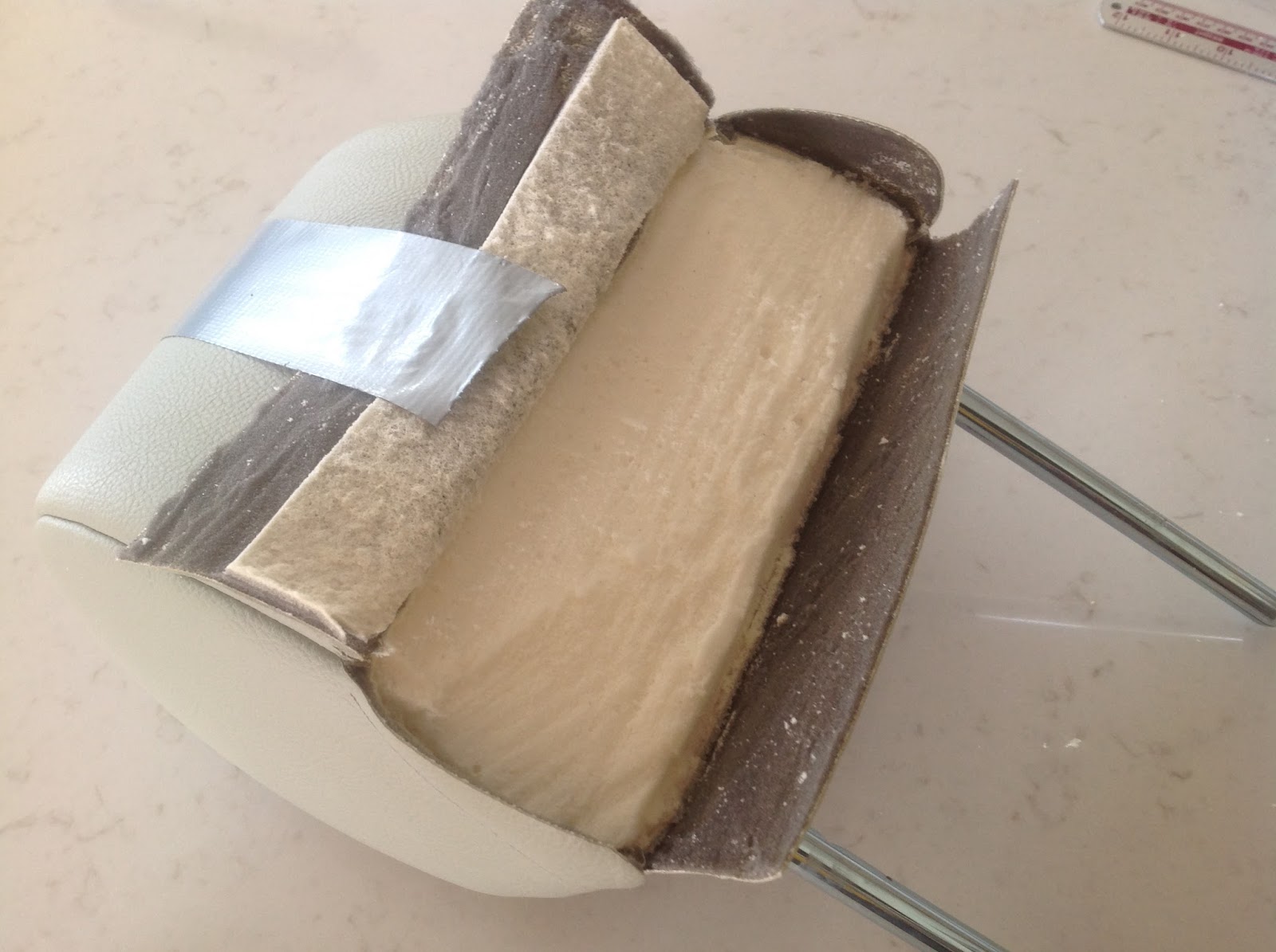
The leatherette was lifted from the foam underneath. The foam that protruded was removed (try a hacksaw to get a smooth surface, but watch you don't cut any leatherette), as was any residual foam still attached to the leatherette of the back, bottom and side flaps. The top flap had about 5mm removed from the across the bottom (the exact amount can be established by pulling the leatherette tight and marking a line across the flap over a flat area of the head restraint, to remove any excess). The side flaps were carefully thinned, then the top flap was thinned for a strip about 12mm deep across the width. The side flap (a triangle) was marked on the reverse of the top flap and this too was thinned.
Head restraint being operated on!
Contact adhesive was applied to the foam, the reverse of the bottom flap, the reverse of the top flap including the thinned area, the reverse of the thinned side flaps, the leatherette faces of the side flaps, the leatherette face of the lower flap (about 10mm across the width). Once touch dry, the bottom flap, followed by the side flaps were pressed in to place. Finally the larger top flap was pressed in to place on to the foam.

The cover was fitted over the head restraint and the new position of the Velcro marked with chalk. The cover was removed, then the Velcro was glued and machine sewn in place. The stitching was redone by hand, down 45mm below the chalk line - both the seam and the top stitch. The remainder of the seams were simply top stitched for continuity. Finally, after refitting the cover again, it was tightened in place, using the Velcro. The remaining bits at the bottom corners were glued in place to make a neat job.
Head restraint in place liberates about 40mm of extra seat travel,
a further 70-75mm is available if the head restraints are not fitted.
The modified head restraints have removed a fair bit of the padding at the bottom back which touched the rear bodywork. This now allows the seats to be pushed back a further 40mm or so.

Wednesday, February 21, 2018

Heated seats part 1 - preparation

So living in the north where it is cold, I have decided to fit heated seat pads to my Cobra's seats. I had said a while ago that any future cars I had with leather seats would always be heated. But in my infinite wisdom decided not to bother for the Cobra - big mistake!

The heat pads for both seats were ordered from Amazon for just £58, including switches, relays and vat. This compares with a 2015 GD price list (which is all I had) at about £300 inc vat. I have decided to fit the switches to the under dash trays to avoid cluttering the dashboard. They have LED indicators showing that the heaters are off or on and at what setting. I may not be able to see the passenger side warning light from the driver's seat, but I should feel the driver's seat warm! This should remind me to check the passenger side.

First the seats were removed by undoing the four nuts and bolts that held each seat in place.
One of the removed seats
A seat base was removed from the seat. The base is held in place by Velcro all around and at the front the leather. I lifted the base from the back, pivoting it towards the front. I then found out that the front was also held in place by some glue, so I had to carefully detach it.
Velcro and glued area on front of seat base
I had expected the back rest to be the most difficult, so I explored this first. The leather was secured with staples at the base.
Staples at base of seat back
These were removed and to my delight the back leather was not stuck to the foam, so the pad can simply be fed up the back and attached with the sticky tape provided.

Next, the leather was released from around the back of the seat base. This Revealed that the leather was stuck to the foam! So I had to remove the staples from all around the seat base. This was a very time consuming process, because I didn't want to damage the leather. The Velcro was left in place on the base, but staples were removed where necessary.
Staples removed all around
Once all the staples that located the leather had been removed - loads of them, I tackled the delightful job of separating the leather from the foam. The leather was glued fully on to the top of the foam seat base. Once the leather was released, I scraped off the remnants of foam and lightly sanded this to remove any that I had missed.
Cleaned up seat base leather (reverse side)
To get to this point took me about 3 hours for one seat. Now for the other!

I have also ordered some upholstery staples to help me put it all back together, along with some contact adhesive.

When the pads arrive I will tackle the installation and wiring of them.

Thursday, February 15, 2018

Stoneleigh National Kit Car Show 2018

The dates for the National Kit Car Show at Stoneleigh in Warwickshire are Sunday 6 May and Monday 7 May. It is the bank holiday weekend.

I will be there, but the weather will dictate if I am in the Cobra or not, as I am still without weather gear for the car! Some of previous displays are below:
Take a brisk ride in a Westfield to get the adrenalin going!
A GD T70 Spyder
The GD stand with a mk3 complete with hardtop
The Ultima stand
A few of the Cobras on display
A mk3R on the GD stand
A mk4 on the GD stand
The AK stand

Thursday, February 01, 2018

Bonnet handles in place of locks ☹️

I wanted to keep clean lines on the Cobra, so I fitted low profile locks on the bonnet, rather than the traditional locking handles. I felt that my car would look better without the handles and still do. However, from a purely practical point of view, the low profile locks make the bonnet difficult to open. The handles do address this issue.

So I splashed out nearly £120 to address the practicality and thereby sacrificed the looks. I bought a set of handles and locking cams from Europa Spares - a benefit is that the bonnet and boot keys are the same. The four M4 raised head machine screws used to fix the handles came from Kayfast.

The existing locks were removed from the bonnet and the new handles were checked for fit. The existing holes were about 2mm bigger than required and had been squared off for the existing locks, but each hole will be covered completely by the handle fixing plate.

The locating pins on the handle fixing plate were removed, as these and the fixing holes were right next to each other, so would have weakened the fixing point. The underside of the fixing plate were then lightly filed to remove the excess metal left after cutting.
Locating pins removed from inner side of each hole on each fixing plate
The two fixing holes on each fixing plate were marked next to the existing holes, before drilling 4.5mm holes through the bonnet.
Two 4.5mm holes drilled each side of existing hole
The handles were temporarily fitted to the bonnet.
Raised head machine screws used to secure fixing plate

The cams were fitted so that the top edge was the same distance from the bonnet as the top of the locating slot.
Locating slot with escutcheon around it
They were then thinned slightly on the bench grinder so that they located in the bulkhead slots. This was a time consuming and faffy job!
Curved surface of cam thinned down 
Once fitted correctly, the machine screws were secured on the underside with nylon nuts and washers.
Bonnet handles fitted in place of locks (a shame)

The boot handle was a straight swap (apart from shortening the square bar) and it looks exactly the same.